Calibrating Shocks for Vulcan Power Armor: A Practical Guide
Learn a practical, step-by-step method for calibrating shocks on Vulcan power armor, covering tools, safety, measurements, tuning, and validation. A guide by Calibrate Point.

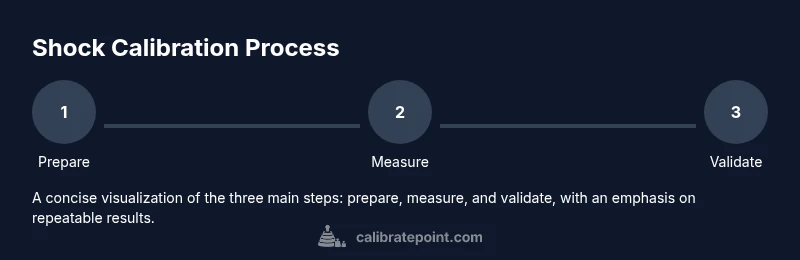
This guide shows how to get calibrated shocks for Vulcan power armor through a structured, step-by-step calibration process. You’ll identify the correct shock model, set up measurement tools, perform baseline tests, tweak damping and travel limits, and validate results under representative loads. Expect safety checks, repeatable procedures, and thorough documentation throughout.
Understanding Calibrated Shocks for Vulcan Power Armor
Calibrated shocks in Vulcan power armor are designed to balance ride quality, mobility, and system responsiveness under dynamic loads. Proper calibration ensures consistent damping, safe travel limits, and reliable feedback to the pilot. According to Calibrate Point, repeatable calibration procedures reduce drift and extend component life. The Calibrate Point team emphasizes documenting each adjustment to track performance over time. In this section, we’ll cover the core concepts, the role of travel and damping, and how calibrated shocks fit into the broader armor control loop. We’ll also distinguish between static calibration, dynamic calibration, and field validation, so you can plan a complete workflow that minimizes downtime and risk. The calibration objective is not simply to reach a target number; it is to achieve predictable response across typical missions, vehicle speeds, and terrain profiles. You will learn how to interpret sensor feedback, define acceptable tolerances, and set up a traceable test record that supports maintenance planning.
System Overview and Prerequisites
To calibrate the shocks, you must understand the shock assembly, the associated sensors, and the armor's dynamic control loop. You need a baseline from the factory specifications and any recent maintenance notes. The installation should be checked for misalignment and wear before testing. This section outlines the primary subsystems involved: shock piston, damper fluid, travel stop, load sensors, and the control algorithms that translate sensor data into actuator commands. Before you start, confirm that the power systems are stable, all safety interlocks are engaged, and you have the proper space to operate with minimal disturbance. A clean, controlled environment helps reduce noise in measurements and improves repeatability of results.
Safety and Compliance Considerations
Calibration work on power armor includes real risk if safety protocols are ignored. Always perform work with power isolated and interlocks engaged. Use appropriate PPE, eye protection, and insulated tools where specified. Establish a lockout/tagout procedure and verify there are no stored energies that could injure personnel or damage systems. Keep a clear boundary around the work area to prevent bystander interference, and document all deviations from standard procedure. Remember that calibration data can influence mission readiness; incorrect steps can compromise safety and performance.
Principles of Shock Calibration
The goal of shock calibration is to align damping characteristics with the armor’s dynamic requirements across a range of loads and speeds. Key factors include damping coefficient, spring pre-load, and travel limit accuracy. Temperature, aging, and fluid condition can shift these properties, so a robust procedure accounts for environmental conditions and component wear. Calibrate Point analysis highlights that calibration should be repeatable and verifiable under controlled, repeatable test conditions. Practical calibration uses a mix of static measurements and dynamic tests to establish a tolerance band that the control system can reliably achieve during operation. Document the intended operating envelope and ensure that the calibrated response stays within that envelope.
Measurement Techniques and Reference Signals
Accurate calibration relies on precise measurements. Use displacement sensors or optical encoders to track piston travel, combined with force sensors to measure damper resistance. Reference signals such as controlled steps, sweeps, and simulated terrain inputs help characterize dynamic response. Record baseline readings with the armor in a neutral position, then perform progressive loads to observe how damping and travel change. Cross-verify sensor data with a calibrated load cell and a stable reference to confirm measurement integrity. Temperature readings should accompany each test to correlate environmental conditions with performance shifts.
Adjusting and Tuning Shocks for Dynamic Range
With baseline data in hand, begin tuning by adjusting damping settings and pre-load as specified in the system manual. Make small incremental changes to valve stiffness, then re-test under the same reference signals to observe shifts in response. Ensure fasteners and alignment remain correct after each adjustment. If travel limits are misaligned, adjust the travel stop and re-check that the piston travel stays within safe bounds. For each adjustment, document the changed parameter, the test conditions, and the observed effect on damping and stability. The aim is to converge on a stable, repeatable response that maintains control fidelity during rapid maneuvers.
Validation Under Simulated Load Conditions
Validate the calibrated shocks by simulating mission-relevant loads: rapid accelerations, braking forces, rough terrain, and sudden direction changes. Compare recorded responses to the target envelope and verify that the armor maintains consistent control authority. If discrepancies appear, revisit the damping curve and re-run the reference tests. Field-like validation helps catch issues that bench tests miss, such as nonlinear behavior at extreme angles or during combined motions. Ensure you keep a revision log for every validation pass.
Maintenance, Documentation, and Next Steps
Calibration is not a one-off task. Schedule periodic rechecks to account for component aging and fluid condition changes. Maintain a calibration log with test numbers, environmental data, tool settings, and operator notes. Use the log to predict when a re-calibration is due and to track performance drift over time. Establish a standard operating procedure for future calibrations so technicians follow a consistent workflow. Finally, review the results with the maintenance lead and plan the next calibration window to minimize downtime during active deployments.
AUTHORITY SOURCES
- https://www.nist.gov
- https://www.iso.org
- https://www.sae.org
Tools & Materials
- Digital Multimeter(For measuring electrical signals and reference voltages.)
- Calibration Rig or Fixture for Shock Assembly(Custom jig to simulate load and measure piston travel.)
- Torque Wrench(With appropriate torque range for fasteners.)
- Calibrated Load Cell(To apply measurable forces during tests.)
- Pressure Sensor Kit(To monitor damper pressure changes.)
- Calibrated Reference Weights(For static load tests.)
- Safety Gear(Gloves, goggles, and protective clothing.)
- User Manual for Vulcan Power Armor System(Reference for system-specific specs.)
Steps
Estimated time: 75-120 minutes
- 1
Power down and secure workspace
Shut down the armor system and isolate the work area. Verify all safety interlocks are engaged and the environment is free of hazards. This ensures you won’t encounter unexpected actuator movements during setup.
Tip: Lockout/tagout and double-check zero-energy state before touching any control interfaces. - 2
Connect diagnostic tools
Attach the digital multimeter and load cell to the relevant test ports on the shock assembly. Verify sensor channels are reporting correctly and that the test rig is securely mounted to prevent movement during tests.
Tip: Label each connector to prevent wiring errors during reassembly. - 3
Inspect shock assembly
Visually inspect for leaks, corrosion, or wear. Check mounting points and alignment with the chassis. Address any obvious defects before proceeding to measurements.
Tip: Replace worn parts before calibrating to avoid skewed results. - 4
Attach calibration rig and zero reference
Mount the calibration rig to simulate a neutral load. Establish a zero-reference measurement to anchor subsequent data. Confirm alignment stays fixed during tests.
Tip: Use a level and laser guide to ensure precise alignment. - 5
Measure travel and damping
Apply a controlled step input and record piston travel, damping force, and velocity. Repeat across several loads to build a damping map. Ensure data is timestamped for traceability.
Tip: Take multiple runs and discard outliers if instrument noise is evident. - 6
Adjust valve and damper settings
Make small adjustments to damping valves and pre-load. Re-test with the same reference signals to observe changes in response. Stop when the readings consistently fall within the target envelope.
Tip: Change only one parameter per test to identify cause and effect clearly. - 7
Validate with simulated load
Run a full dynamic test sequence that mimics mission conditions, including rough terrain and rapid accelerations. Check consistency of the control response across cycles.
Tip: If variation exceeds tolerance, revisit Step 6 and refine incrementally. - 8
Document results and schedule next calibration
Log all test data, tool settings, environmental conditions, and operator notes. Schedule the next calibration window based on wear indicators and mission tempo.
Tip: Keep a certified copy of the calibration file for audits.
Questions & Answers
What is the primary goal of calibrating shocks for Vulcan power armor?
The goal is to achieve a repeatable, predictable damping response that maintains control authority under typical mission loads. Calibration aligns damper characteristics with the armor's control loop and safety limits.
The aim is a repeatable damping response that keeps you in control during missions.
Which tools are essential for the calibration process?
You need a calibrated measurement setup including a digital multimeter, load cell, displacement sensors, and a calibrated test rig. The armor manual will specify torque ranges and fastener requirements.
A calibrated measurement setup and the armor manual are essential.
Can I calibrate shocks in the field or only in a workshop?
Field calibration is possible with portable test rigs and controlled conditions, but most precise work benefits from a workshop environment with stable power and temperature.
Field work is possible with portable tools, but a workshop offers better accuracy.
How often should calibration be repeated?
Frequency depends on usage, environment, and wear. Establish a maintenance interval based on manufacturer guidelines and observed drift in test data.
Calibrate based on usage and wear, following a scheduled maintenance plan.
What are common signs of miscalibration?
Unstable control response, increased oscillations, lag in damping, or unusual travel limits indicate calibration drift or component wear.
Unstable feel or unusual travel suggests drift or worn parts.
Watch Video
Key Takeaways
- Plan calibration within a controlled environment.
- Use precise tools and document every measurement.
- Validate results against mission-relevant loads.
- Schedule and log follow-up calibrations for maintenance.