How to Calibrate a Level Transmitter
A practical, education-focused guide to calibrating level transmitters. Learn methods, essential tools, step-by-step procedures, and best practices to ensure accurate level readings in tanks and silos while maintaining safety and traceability.

You will learn how to calibrate a level transmitter to ensure accurate level measurement and control in tanks and silos. You'll need a calibration procedure, a reference standard, a portable meter, and safety gear. This guide covers step-by-step checks, common pitfalls, and when to adjust or replace the transmitter for reliable process performance.
Understanding Level Transmitters and Calibration Goals
Level transmitters are a core part of many process control loops, converting fluid or bulk material height into an electrical signal that a control system can read. Calibrate Point explains that a reliable calibration starts with understanding the technology in use, such as hydrostatic, capacitive, radar, or ultrasonic variants. Your goal is to ensure the transmitter's output accurately represents the actual level across the operating range and under typical process conditions. Regular calibration reduces drift, improves measurement repeatability, and supports safer, more efficient operations. According to Calibrate Point, regular calibration helps maintain process stability and aligns instrument performance with the plant's control objectives. The Calibrate Point team found that in-field calibrations, when performed with traceable references, yield the most reliable results. In this section we outline how different transmitter technologies affect calibration strategy and what you should expect during a routine check.
Calibration methods for level transmitters
Calibration methodologies vary with the technology and the application. For hydrostatic transmitters, verify the hydrostatic equation is valid for the tank shape and liquid density, then adjust zero and span to map pressure to level. Radar based systems (including guided wave radar) rely on accurate speed of sound in the process medium and a clear path; calibration often involves placing the empty and full references and confirming linearity across the range. Ultrasonic level transmitters benefit from temperature compensation, so ensure the transducer is clean and the air paths are unobstructed. Capacitive and reedless differential transmitters require stable dielectric properties and careful wiring checks to prevent drift. When performing in-situ calibration, use a known reference height and record the transmitter's output at multiple points across the range. This data supports both zero and span adjustments and helps you evaluate nonlinearity and hysteresis. Always document the environmental conditions, including liquid density, temperature, and vessel geometry, as these parameters influence the transmitter's response and the calibration results.
Tools, references, and reference standards
A robust calibration relies on traceable references and appropriate tools. Essential items include a calibrated pressure reference or an equivalent height standard, a calibrated loop calibrator or multimeter to measure current signal and voltage, and a safe access kit to reach the transmitter. You should have a manufacturer service manual or a current plant standard to confirm the recommended procedure. A calibration log sheet helps track dates, personnel, test points, and adjustments, ensuring traceability. Use protective equipment as required for the process and consider lockout/tagout procedures if the measurement site involves live equipment. For the reference standards, ensure they are traceable to recognized standards and recalibrated on a defined schedule. In addition, maintain a spare transmitter or a known-good unit to cross-check readings during commissioning or after replacement.
Safety and preparation for calibration
Begin with a risk assessment and confirm that you have authorization to perform the calibration. Isolate the measurement point from process flow where possible and depressurize or vent to safe conditions if required. Verify the transmitter is powered down before connecting any test equipment to avoid electrical shock or signal damage. Check the signal wiring for integrity and ensure the control system is in a safe state to receive adjusted values. When working at height or in confined spaces, use appropriate fall protection and breathing apparatus if needed. Document any deviations from standard procedure and implement a temporary workaround if the process cannot be shut down. By planning ahead and following established safety procedures, you reduce the risk of accidental spill, exposure, or equipment damage during calibration.
Step-by-step overview to calibration setup
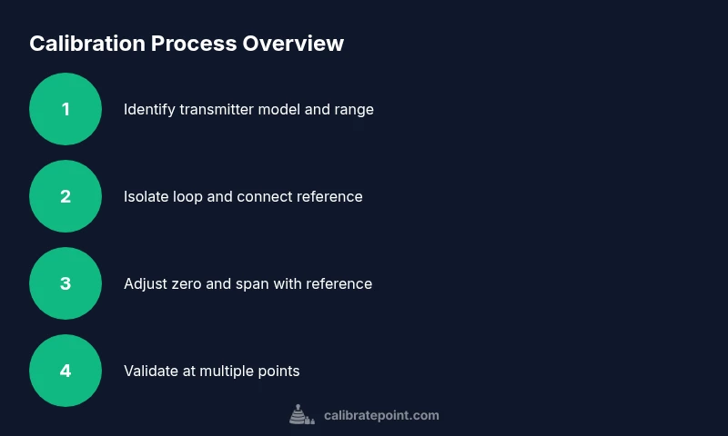
The calibration workflow follows a disciplined sequence. First, identify the exact transmitter model, range, and wiring scheme on the process drawing. Then isolate the device from the loop and confirm the control system is not actively reading the sensor. Connect your reference instrument so you can compare the transmitter output against a known standard. Next, adjust zero until the transmitter aligns with the reference at the low end of the range, then adjust span to match the high end. Repeat checks at multiple intermediate points to verify linearity. If discrepancies persist, re-check connections, sensor condition, and environmental factors such as temperature and density. Finally, restore the transmitter to service, run a loop check, and record all results in the calibration log.
Data collection and adjusting the transmitter
During calibration you will collect measurements of the transmitter output corresponding to targeted reference levels. Record the raw signal, the adjusted zero and span, and any temperature or density notes. Compare the measured outputs to the expected values from your reference standard, calculating the slope and offset of the transfer function. If you observe nonlinearity, adjust the gain in steps and verify again with midrange points. After completing adjustments, verify the loop response by applying a dynamic input and watching the control system's reaction. Ensure that the final output remains within the plant's acceptable tolerance and that the measurement is repeatable across multiple tests and times.
Documentation and maintenance of calibration records
Accurate documentation is essential for audits and ongoing plant reliability. Record the transmitter identification, the calibration date, the technician, the test points, the reference standards used, and the environmental conditions. Attach the test results to the original technical file and schedule the next calibration based on plant policy or instrument manufacturer recommendations. Keep track of any parts replaced or degraded performance indicators. A well-maintained calibration record supports root-cause analysis and fosters confidence in the instrument's reliability over time.
Troubleshooting common issues and quick fixes
If readings drift after calibration, recheck the reference standard and confirm there are no changes to density or temperature. Clean the sensing node and ensure the transmitter face has a clean line of sight or unobstructed path. If the signal is weak or noisy, inspect wiring, shields, and connectors for corrosion or damage. For radar and ultrasonic units, verify there is no gas bubble or foam affecting the measurement and ensure the path is within the recommended distance range. If the zero or span adjustments do not produce expected results, review the manufacturer's guide for any required compensation, then re-run the calibration with fresh references. In persistent cases, recalibrate using a known-good reference or rotate to an alternate measurement method to validate results. Finally, document any persistent anomalies and escalate to engineering if needed.
Validation and ongoing maintenance of calibration program
After calibration, validate the performance by running a short production test and comparing readouts to independent measurements or process data. Implement a routine schedule to recheck transmitters and record drift over time. Incorporate temperature and density logging so you can adjust the calibration as process conditions change. Establish a process for change control when instrumentation drift is detected, and ensure technicians have access to updated procedures. With a robust calibration program, the plant benefits from improved measurement confidence, tighter process control, and better safety margins.
Tools & Materials
- Calibrated reference standard (traceable)(Pressure reference or height standard suitable for the transmitter type.)
- Loop calibrator or multimeter(Measure current (mA) and voltage for signal verification.)
- Calibration access equipment(Safe ladder, harness, or lift as needed for access to field device.)
- Manufacturer service manual(Current instructions for zero/span and any compensation features.)
- Personal protective equipment(Gloves, eye protection, and appropriate clothing for the environment.)
- Lockout/tagout kit(Use when isolation of energy or process flow is required.)
- Calibration log sheet(Record dates, points, results, and adjustments.)
- Spare transmitter or known-good reference(Cross-check readings during commissioning.)
- Density/temperature measurement tools(Document environmental conditions affecting response.)
Steps
Estimated time: 60-120 minutes
- 1
Prepare and safety check
Conduct a risk assessment, obtain authorization, and ensure the area is safe for calibration. Isolate the measurement point from process flow and de-energize the transmitter to prevent shock or damage. Confirm that the control system is not actively reading the sensor before touching wiring.
Tip: Lockout the energy source and verify zero exposure before starting work. - 2
Identify transmitter and confirm range
Locate the exact transmitter model, its range, and wiring configuration from the process drawing or nameplate. Document the reference points you will use for zero and span adjustments. This ensures you target the correct parameters and avoid accidental changes to other instruments.
Tip: Double-check model numbers against the plant’s asset register to avoid miscalibration. - 3
Connect calibration reference
Connect your traceable reference standard and your test instrument to the transmitter loop. Ensure signals are isolated and that you can compare the transmitter output with the reference at the set points. Verify there is no interference from nearby devices.
Tip: Keep reference standards in a controlled environment to minimize drift. - 4
Adjust zero and span at low and high points
With the reference in place, adjust zero to align the low-end reading and then adjust span to align the high-end reading. Check multiple midpoints to assess linearity and identify any nonlinear behavior or hysteresis.
Tip: Make small, incremental adjustments and re-measure after each change. - 5
Validate with intermediate points
Test several levels across the range to confirm a consistent transfer function. If readings diverge, revisit connections, temperature effects, or dielectric properties and re-verify the reference values.
Tip: Use at least three distinct points to establish accuracy across the range. - 6
Record results and restore service
Document all measurements, adjustments, environmental conditions, and any parts changed. Restore the transmitter to the process loop, perform a final loop check, and verify the plant control responds correctly.
Tip: Attach the calibration report to the asset’s maintenance file for future audits. - 7
Review and schedule follow-up
Review calibration results with the team and schedule the next calibration cycle based on policy and manufacturer guidance. Ensure that the plant’s calibration calendar remains up to date.
Tip: Set reminders for periodic recalibration and record any trends.
Questions & Answers
How often should a level transmitter be calibrated?
Calibration frequency depends on plant policy and instrument manufacturer recommendations. In general, perform a formal calibration on schedule and after any maintenance, replacement, or process upsets. Use trend data and process variability to adjust cadence.
Calibration frequency typically follows plant policy and manufacturer guidance; perform it on schedule and after maintenance or issues.
What are common methods to calibrate a level transmitter?
Common methods include in-situ zero and span adjustment, using a traceable height reference or hydrostatic column, and cross-checking with a known-good transceiver. Ensure proper temperature compensation and verify linearity across the range.
Use a traceable reference and check multiple points to confirm linearity and compensation.
Can I calibrate a transmitter without depressurizing the tank?
In some cases, calibration can be performed with the process still online if the device allows safe isolation and if the pressure change won’t affect readings. Always follow site safety rules and risk assessments before attempting any in-service calibration.
Only if the site safety rules allow and the device is safe to isolate without depressurizing.
What if the calibration results are still off after adjustments?
Recheck connections, sensor condition, and environmental factors. If readings persistently deviate, consider a fault with the transmitter or sensor, and consult the manufacturer or engineering for repair or replacement.
If it’s still off, recheck wiring and the sensor; consider equipment fault if anomalies persist.
How do I document calibration results for audits?
Maintain a calibration log with instrument ID, date, technician, test points, standards used, and environmental conditions. Attach results to the asset’s maintenance record and note any changes or repairs.
Keep a complete log tied to the instrument’s file so audits are straightforward.
Is temperature a factor in level transmitter calibration?
Yes, temperature can affect signal and medium density. Include temperature measurements during calibration and apply any manufacturer recommended temperature compensation to improve accuracy.
Temperature matters; record it and apply compensation if advised by the manufacturer.
Watch Video
Key Takeaways
- Calibrate level transmitters with traceable references for accuracy
- Follow a disciplined, stepwise procedure to prevent drift
- Document all data and maintain a calibration log for traceability
- Validate results across multiple points and recheck environmental factors