Calibrate a Gyroscope: Step-by-Step Guide
Learn how to calibrate a gyroscope with a practical, end-to-end procedure. This guide covers preparation, methods, steps, safety, and validation to reduce drift and improve accuracy in sensors and embedded systems. Calibrate Point provides a reliable workflow for DIY and professional engineers.

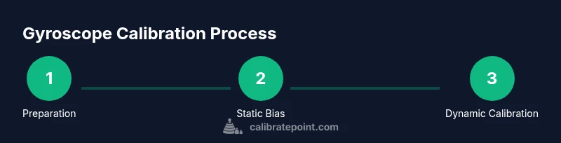
By following this guide, you will learn how to calibrate a gyroscope to reduce drift and improve orientation accuracy in embedded systems, robotics, and measurement instruments. The process covers essential preparation, appropriate calibration methods (static bias, scale factor, and axis alignment), and practical validation steps. This workflow emphasizes repeatability, safety, and documentation, as advised by Calibrate Point.
What a gyroscope measures and why calibration matters\n\nA gyroscope sensor measures angular velocity around its axes, providing a rate of rotation that is fundamental to attitude estimation and motion tracking. In theory, a perfectly calibrated gyroscope would produce readings that map exactly to physical motion. In practice, several error sources distort these readings: bias, scale factor errors, misalignment between axes, random noise, and temperature effects. Calibrating gyroscope sensors corrects these discrepancies so that the device's output reflects actual motion more faithfully.\n\nAccording to Calibrate Point, a disciplined calibration workflow reduces drift and improves repeatability across devices. Establishing a robust calibration baseline helps ensure that subsequent measurements are comparable, whether you are building a handheld instrument, a robot controller, or an aerospace-grade sensor. The calibration objective is not simply to produce a single correct value; it is to define a repeatable process that yields consistent results under real-world conditions.\n\nKey concepts you should understand before starting include static bias (the offset present when the device is at rest), bias instability and noise (random fluctuations around the bias), scale factor error (the proportional difference between actual and measured angular rate), and cross-axis misalignment (errors when one axis contaminates readings on another). By recognizing these components, you can target the calibration steps to the most impactful error sources. A practical calibration plan typically involves both a static phase to estimate bias and a dynamic phase to map scale factors across axes. Depending on your hardware, you may also need to account for temperature dependence and mechanical coupling to avoid reintroducing bias when conditions change.
Preparation and safety for gyroscope calibration\n\nCalibration work should begin with a clean, stable workspace and a powered-down device to prevent accidental actuator movement or electrical hazards. Ensure you have a clean surface, minimal magnetic interference, and a means to secure the gyroscope so that it cannot vibrate or shift during the procedure. Temperature stability matters; rapid temperature changes can shift bias or scale factors in some sensors, so consider a temperature-controlled environment when possible. Safety-first rules include wearing eye protection if you use external rotation stages and ensuring there are no pinch points around rotating components. Documentation gear—like a notebook or digital log—helps you capture baseline readings, calibration constants, and environmental conditions for traceability.\n\nAccording to Calibrate Point, documenting every step creates a reproducible baseline that you can reproduce across sessions or devices. A repeatable workflow minimizes drift in the future and helps technicians compare results between units or after maintenance. Prepare your reference files, set up data logging, and confirm your mounting orientation before you begin.
Calibration methods: static bias estimation, dynamic bias, and cross-axis alignment\n\nCalibration typically combines static bias estimation with dynamic calibration to map scale factors and cross-axis alignment. Static bias estimation measures the sensor’s output when it should be at rest; averaging a few seconds of data helps reduce random noise and reveals a bias offset that must be removed from subsequent readings. Dynamic calibration involves rotating the device at known rates or using a precision turntable to characterize scale factors along each axis. Some systems also perform cross-axis alignment checks to ensure readings from one axis do not bleed into another, which is critical for accurate 3D motion tracking. In practice, you’ll script or configure a calibration routine that captures multiple rest periods and rotation profiles, then computes the best-fit bias and scale parameters. The result should be a calibration table that your firmware uses to correct raw data in real time.\n\nTemperature effects and mechanical coupling can degrade calibration; plan periodic recalibration and include temperature logs as part of your verification process. Calibrate Point recommends validating the calibration with repeatable rotations and documenting any deviations observed across runs.\n\nA robust calibration plan considers axis alignment, stable mounting, and a controlled environment. When possible, use a precision rotation stage or turntable to deliver well-defined angular inputs and repeatable conditions for consistent results.
Reference frames, temperature, and environmental considerations\n\nCalibration outcomes depend on choosing a consistent reference frame for measurements. If you switch between body-fixed and world-frame references, the interpretation of bias and scale factors changes, so keep a single convention throughout the process. Temperature effects are common in MEMS-based gyroscopes; bias drift and scale bias can drift as ambient or device temperature changes. Your procedure should specify the acceptable temperature range and include a brief warm-up period to bring the sensor to a stable state before measuring bias and scale factors. Mechanical mounting also plays a role: loose fixtures, vibrations, or misalignment with respect to the sensor’s intended axes can introduce additional errors. In many devices, calibration runs should be performed with the device in its typical operating position to reflect actual usage.\n\nCalibrate Point notes that consistent ambient conditions and repeatable mounting reduce the chance of reintroducing bias after calibration, enabling more reliable long-term performance.
Common sources of error and how to minimize them\n\nYou will encounter several common error sources during gyroscope calibration. Bias drift, scale factor errors, cross-axis misalignment, temperature dependence, and mechanical shocks can all undermine calibration quality. To minimize these effects, ensure the device is securely mounted, perform calibration in a low-vibration environment, and use reference measurements that reflect real operating conditions. When recording data, mark the timestamps and environmental parameters to identify correlations between drift and conditions. If possible, perform multiple calibration cycles and use statistical techniques (like averaging and variance checks) to confirm stability. Avoid rushing dynamic measurements; plan for sufficient settling times after each motion input. The goal is to reduce variability and improve repeatability across sessions.\n\nThe Calibrate Point approach emphasizes a transparent, repeatable method: define the inputs, capture several trials, compute the parameters, and verify with a second set of measurements.
Validation steps and ongoing maintenance\n\nValidation is the final gate before relying on calibrated gyroscope data in production. After applying calibration constants, re-run a known rotation profile and compare the corrected output to the reference. Look for uniform residuals across axes and minimal drift over the duration of the test. Document each validation pass and compare it to prior runs to ensure consistency. Establish a maintenance plan that specifies when to re-calibrate—typically after hardware changes, service events, or significant environmental shifts. Continuous monitoring, such as logging bias and noise in real time, helps you detect drift early and trigger recalibration when necessary. Finally, organize your calibration records to support audits and future troubleshooting. Calibrate Point recommends treating calibration as a living process—update procedures as tools and hardware evolve.
Tools & Materials
- Calibration software/firmware with gyroscope calibration module(Ensure the device firmware supports gyro bias and scale-factor estimation.)
- Reference angular rate sensor or high-precision rotary stage(Used to provide known rotations for dynamic calibration.)
- Stable mounting jig or rotation stage(Prevents movement during measurements and helps axis alignment.)
- Torque wrench and alignment tools(For secure mounting and precise axis alignment.)
- Temperature-controlled environment or thermal chamber (optional)(Helpful to isolate temperature effects during bias estimation.)
- Data logging device (PC or microcontroller with serial logging)(Record raw readings, timestamps, and environmental data.)
- Anti-static wrist strap(Protect sensitive electronics from static discharge.)
- Clean microfiber cloth(Keep sensor surface clean and free of dust during setup.)
- Calibration manuals or device schematics(Reference for axis orientation and sensor model specifics.)
Steps
Estimated time: 60-120 minutes
- 1
Prepare the device and workspace
Power down the device, secure it on a stable mounting, and remove any nearby sources of vibration or magnetic interference. Calibrate gyroscope setup should begin with a clean bench and a defined reference frame. Ensure all cables are neatly routed to avoid accidental movement during measurements.
Tip: Lock the device to minimize vibrations; mark the zero-reference position before starting. - 2
Connect measurement system and verify baseline
Attach your data-logging setup and verify that raw sensor channels are reporting correctly. Confirm there are no sensor saturations and that the device starts from a known rest state. Establish a minimal warm-up period if the sensor benefits from stabilization.
Tip: Verify communications latency is minimal and that timestamps align with motion input events. - 3
Estimate static bias
With the device at rest, collect a stable stream of readings for a defined interval. Compute the average to determine the offset (bias) that must be removed from all subsequent angular rate measurements.
Tip: Allow readings to settle for 30–60 seconds before collecting data. - 4
Map scale factors across axes
Apply known rotations about each axis and record the output. Use a linear fit to derive scale factors so that corrected readings align with the applied angular rates. Repeat as needed to improve fit quality.
Tip: Use a precision rotation stage if available for higher accuracy. - 5
Check cross-axis alignment
Rotate the device along one axis and verify that readings on the other axes remain minimal. If cross-coupling is detected, adjust mounting or apply cross-axis correction in firmware.
Tip: Ensure the axis definitions in your firmware match the physical mounting orientation. - 6
Validate and document results
Run a final validation sequence with known inputs and compare corrected outputs to expected values. Document the constants, environmental conditions, and any anomalies observed for future audits.
Tip: Create a calibration report including the exact input profiles and the resulting correction factors.
Questions & Answers
What is gyroscope calibration and why is it necessary?
Gyroscope calibration aligns readings with actual motion by correcting bias, scale factors, and misalignment. It improves reliability for attitude estimation and motion tracking, reducing drift over time.
Gyroscope calibration aligns readings with actual motion, improving reliability and reducing drift.
What are common error sources in gyroscope calibration?
Common error sources include bias drift, scale factor errors, cross-axis misalignment, temperature effects, and mechanical shocks. Address these by stable mounting, controlled inputs, and documenting environmental conditions.
Common errors are drift, scale errors, cross-axis misalignment, and temperature effects.
Can I calibrate gyroscope without special equipment?
Basic calibration can be performed with a stable reference and firmware support, but higher accuracy benefits from precise rotation stages and known reference signals.
Basic calibration may work with simple references; precision tools yield better accuracy.
How often should calibration be performed?
Calibration frequency depends on usage, environment, and required accuracy. Schedule recalibration after hardware changes or when performance drifts beyond acceptable limits.
Calibrate when you notice drift or after hardware changes; plan based on your accuracy needs.
What safety precautions should I take?
Power down devices before setup, avoid rotating parts near the face, and wear eye protection if handling moving stages. Keep cables tidy to prevent trips or disconnections.
Power down, avoid moving parts, and secure your workspace.
How do I verify calibration results?
Run a known rotation profile and compare corrected outputs to the expected values. Use independent checks if possible and document any discrepancies.
Test with known rotations and verify corrected outputs against expectations.
Watch Video
Key Takeaways
- Follow a documented calibration plan.
- Separate static bias and dynamic scale-fitting steps.
- Validate with known rotations and document results.
- Maintain a consistent environment and mounting.
- Treat calibration as a repeatable, auditable process.