How to Calibrate a MAP Sensor: Step-by-Step Guide
Learn how to calibrate a MAP sensor with a practical, safety-focused step-by-step approach. Tools, steps, tips, and cautions for reliable manifold pressure readings.

You will learn how to calibrate a MAP sensor to improve fuel trim and idle stability. This involves verifying sensor voltage with a regulated vacuum source, comparing readings to a known pressure, and adjusting ECU data or replacing the sensor if needed. You’ll need a pressure source, a multimeter, and a scan tool.
MAP calibration matters for engine performance
MAP sensors measure manifold absolute pressure to help the ECU calculate air density and fuel delivery. Accurate MAP readings translate into smoother idle, better throttle response, and improved fuel efficiency. According to Calibrate Point, small MAP drift can degrade fueling accuracy, especially during rapid throttle changes or cold-start conditions. In modern engines, calibration isn't just about replacing a faulty sensor—it's about validating the sensor's output against a known reference and documenting the results for maintenance records. This section covers the fundamentals and why a careful calibration workflow matters for reliability and performance. By understanding the sensor's role, you can design a calibration plan that minimizes variables such as temperature, humidity, and supply voltage. The goal is to establish a traceable baseline that you can reproduce across service intervals, tools, and technicians. This builds confidence when diagnosing drivability issues and demonstrates professional calibration discipline.
How MAP sensors work and what calibration achieves
A MAP sensor typically outputs a voltage that changes with the pressure in the intake manifold. The ECU converts this signal into an air density value to adjust fuel delivery. Calibration aligns the sensor's electrical output with true pressure across the operating range (vacuum to boost). If the sensor is biased or drifting, fueling tables can become skewed, especially at mid-range loads. Calibrate Point analysis shows that even minor sensor drift can lead to rich or lean conditions during acceleration. The calibration process sets the sensor's transfer function to match the engine's expected response, ensuring predictable throttle, smoother idle, and reduced emissions. Achieving this requires stable measurement conditions, proper references, and a repeatable test setup so results are defensible and actionable.
Indicators that your MAP sensor needs calibration
Diagnosing MAP sensor issues begins with symptoms rather than guesses. Common signs include rough idle, fluctuating fuel trim, hesitation during acceleration, and occasional loss of power under load. A malfunctioning sensor can trigger fault codes or cause the ECU to run an overly rich or lean map. Calibrate Point analysis shows that many issues attributed to a faulty MAP stem from calibration drift or wiring inconsistencies rather than a dead sensor. Before jumping to replacement, verify the sensor's output against a known reference and check the wiring harness for shorts, corrosion, or loose connections. Document observed voltages and compare them to factory specifications, if available, to guide next steps.
Calibration approaches and accuracy considerations
There are several ways to calibrate a MAP sensor, depending on the vehicle and the testing environment. Bench testing with a regulated vacuum source allows you to map sensor voltage to actual pressure in a controlled setting. On-vehicle calibration can be more complex due to engine temperature, air intake conditions, and turbulence, but it yields results that directly reflect real-world driving. Accuracy depends on the stability of the pressure source, the sensor's electrical connections, and the ECU's interpretation. When in doubt, use traceable references and document the tolerances you expect. Calibrate Point emphasizes documenting all measurements to support future diagnostics and to provide a reproducible calibration record for the fleet or workshop.
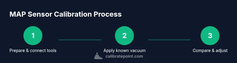
Practical calibration workflow: testing, comparing, and adjusting
A disciplined calibration workflow combines measurement, comparison, and validation. Start by powering down safely and preparing a clean test area. Use a known reference pressure, record the MAP voltage, and log the corresponding pressure using a calibrated gauge. Compare your results to the ECU's expected values and adjust the sensor mapping or ECU calibration as permitted by the toolset. Validate with another data run at the same conditions to confirm repeatability. Finally, document the final readings, calibration offsets, and any changes made to the ECU or wiring. This approach minimizes guesswork and produces auditable results. The Calibrate Point team recommends a written calibration protocol for every vehicle and toolset to ensure consistency across technicians.
Safety and best practices for calibrating sensors
Calibration work involves electrical testing and controlled pressure applications, so safety is essential. Always disconnect the battery when wiring changes, wear eye protection, and handle the pressure source with care to avoid leaks or bursts. Use a regulator that stays within the MAP sensor's rated pressure range, and never exceed the sensor’s documented limits. Keep test data organized and labeled by vehicle, sensor serial, and environmental conditions. Following these practices protects you and preserves data integrity for future maintenance.
Putting calibration into practice: what Calibrate Point recommends
Effective MAP sensor calibration hinges on using a controlled test bench that isolates variables, reproduces pressures, and records results consistently. The Calibrate Point team emphasizes using traceable references, documenting baseline measurements, and validating outcomes with engine runs when possible. A thorough calibration plan reduces diagnostic guesswork and supports reliable maintenance records. The takeaway is to treat calibration as a repeatable process rather than a one-off adjustment, ensuring dependable performance over time.
Tools & Materials
- 12V automotive battery(Fully charged; use a test bench or disconnect to prevent shorts during wiring checks)
- Digital multimeter (DMM)(Must read 0–5V (or sensor-specific range); verify probe connections are secure)
- Regulated vacuum/pressure source(Capable of delivering 0–60 kPa (or sensor's range); include regulator and hoses)
- Vacuum gauge or manometer(Optional but recommended to verify applied pressure precisely)
- OBD-II scanner or ECU data logger(To read live MAP voltage and correlate with ECU fuel trims)
- Wiring adapters and test leads(Include suitable connectors for MAP harness; keep spare pins and clips)
- Safety equipment(Safety glasses, gloves; protection against leaks and electrical hazards)
- Vehicle service manual or calibration table(Provides reference values and procedure specifics for the target model)
Steps
Estimated time: 45-90 minutes
- 1
Power down and prepare the workspace
Power off the engine and disconnect the battery ground to prevent accidental shorts while probing sensors. Confirm the area is clean and free of fuel vapors. Take photos of wiring before you disconnect anything to aid reassembly.
Tip: Photo-document connections before unplugging; this reduces reassembly errors. - 2
Locate MAP sensor and inspect wiring
Find the MAP sensor on the intake manifold or throttle body. Inspect the harness for corrosion, loose connectors, or damaged wires. A clean, intact connector reduces noise and intermittent readings.
Tip: Refer to the service manual for the exact sensor location and pinout to avoid misreading signals. - 3
Set up measurement apparatus
Attach the regulated vacuum source to the MAP sensor vacuum port and connect the DMM to measure the sensor output voltage. Verify all connections are tight and the pressure source is stable before starting measurements.
Tip: Stabilize the pressure for 30 seconds before recording values to avoid transient spikes. - 4
Record baseline readings
With engine off but ignition on (to power the sensors), record the MAP voltage at known reference pressures. Document ambient temperature as it affects sensor behavior. Create a baseline you can compare against during calibration.
Tip: Log multiple readings at each reference pressure to assess repeatability. - 5
Apply known vacuum and capture readings
Progressively apply a set of known pressures within the sensor's range and record the corresponding voltages. Ensure you cover the full operating envelope: low vacuum, mid-range, and near the sensor limit.
Tip: Avoid rushing; incremental steps improve accuracy and reduce hysteresis effects. - 6
Compare readings to ECU data and adjust
Compare the measured sensor-to-pressure relationship with the ECU's expected map. If allowed, adjust ECU calibration offsets or, if necessary, replace the sensor. Re-check after any adjustment to confirm improved alignment.
Tip: Keep a clear record of offsets and why each change was made. - 7
Re-test under engine conditions
Reconnect the battery, start the engine, and monitor MAP readings during idle and acceleration. Confirm that the ECU responds to MAP changes as expected and that fuel trims stabilize.
Tip: Perform a short drive cycle to verify real-world performance after bench calibration.
Questions & Answers
What is MAP sensor calibration, and why is it necessary?
MAP sensor calibration aligns the sensor's electrical output with actual manifold pressure across the operating range. It helps ensure accurate fuel delivery and idle performance, reducing drivability issues. Regular calibration can extend sensor life and improve diagnostic confidence.
MAP calibration aligns sensor output with actual pressure to improve fuel delivery and idle quality. Regular checks help prevent drivability problems.
Can MAP sensor calibration be performed without starting the engine?
Yes. Bench calibration uses a regulated vacuum source and measurement tools on a test bench, avoiding engine start-up. This approach isolates variables and allows precise mapping of sensor response to known pressures.
Yes, you can calibrate MAP sensors on a bench with a vacuum source, without running the engine.
What are common signs that a MAP sensor needs calibration?
Common signs include rough idle, fluctuating fuel trim, hesitation on acceleration, and occasional misfires. If readings drift or don’t match ECU expectations, calibration or sensor replacement may be necessary.
Rough idle and erratic fuel trim often point to MAP sensor drift; calibration or replacement may be needed.
What tools are essential for MAP sensor calibration?
Essential tools include a digital multimeter, a regulated vacuum source, and an OBD scanner or ECU data logger. Optional items include a vacuum gauge and a service manual for reference values.
You need a multimeter, a vacuum source, and an ECU data logger; a vacuum gauge helps but isn't mandatory.
Should the MAP sensor be replaced instead of calibrating if drift is detected?
If calibration attempts fail to align sensor output with reference data or if the sensor shows persistent drift beyond tolerance, replacement is usually the correct path. Start with confirming wiring integrity and recalibration before replacing.
If calibration fails or drift remains beyond spec, replacement is typically recommended after checking wiring.
Watch Video
Key Takeaways
- Calibrate MAP sensor with known pressures and measure output voltages.
- Use a regulated vacuum source and stable connections.
- Compare results to ECU data and document offsets.
- Re-test under engine conditions to confirm results.