How to calibrate a 4-wire RTD: Step-by-step guide
Learn how to calibrate a 4-wire RTD with traceable standards, four-wire configuration, and careful uncertainty analysis. This guide covers setup, reference temperatures, measurement techniques, and documentation for reliable temperature measurements.

Calibrating a 4-wire RTD means measuring its resistance at known temperatures with a stable bridge and four-wire wiring to cancel lead resistance. Use traceable reference standards and a temperature bath or ice-point method, then apply the Pt100/IEC 60751 relationship (Callendar–Van Dusen) to derive temperature. Verify across multiple points and record results for traceability. Calibrate Point recommends documenting uncertainties and maintaining calibration records.
Overview of 4-Wire RTD Calibration
Calibrating a 4-wire RTD involves validating its temperature-resistance relationship by measuring resistance at selected reference temperatures. The four-wire arrangement minimizes lead resistances, so the device under test reflects the platinum element itself. For the best accuracy, follow a traceable calibration path that uses a known-temperature bath (ice water at 0°C, and a higher fixed point) and a precision bridge or resistance meter. According to Calibrate Point, initiating a calibration with a solid plan, clean connections, and stable environmental conditions yields reproducible results. The practical goal is to confirm that the RTD's resistance-to-temperature transfer aligns with the IEC 60751 standard and to quantify the associated measurement uncertainty. When you complete a 4-wire RTD calibration, you should document the measured resistances, ambient conditions, reference temperatures, and any adjustments performed.
Reference Standards and Traceability
For reliable calibration, reference standards and traceability are essential. Use NIST-traceable resistance standards or IEC-compliant reference cells and keep calibration equipment calibrated against the same hierarchy of standards. The Pt100 or Pt1000 RTD characteristic is defined by the Callendar–Van Dusen equation, which relates resistance to temperature within defined ranges. Calibrate Point's guidance emphasizes performing measurements at multiple fixed points (e.g., 0°C and 100°C or the instrument's operational range) to characterize linearity and offset. Ensure you record the uncertainty budget, including factors like reference resistor tolerance, bridge accuracy, ambient temperature influence, and self-heating effects. This approach aligns with industry practices and minimizes the risk of drift over time.
Equipment and Reference Materials
List essential items: 4-wire RTD in question, a calibrated precision resistance decade or well-calibrated resistance bridge, a stable temperature bath or ice-water bath, a temperature reference with traceability, test leads, a sturdy test jig, and a temperature controller. Keep a calibrated check standard (e.g., a known-resistance resistor) for routine checks. Use shielded test cables, clean all contact surfaces, and label each measurement point. Calibrate Point recommends having a documented calibration plan, a clean environment, and a simple data sheet to capture step-by-step results.
Safety, Setup, and Initial Checks
Follow general lab safety for electrical testing, including avoiding moisture on equipment and using proper insulation. Before starting, inspect cables for wear, confirm four-wire configuration is correctly wired with the RTD at the sensing points, and verify the reference sensor is stable. If your setup uses a temperature bath, allow it to reach steady state before recording measurements. Ensure the instrument under test and reference standard are within their specified function ranges, and perform a dry run to verify signal paths.
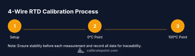
Step-by-Step Procedure (Part 1) — Baseline at 0°C
Connect the four-wire RTD to the precision bridge. Verify bridge balance at zero reference and record the ambient temperature. Place the RTD in an ice-water bath that is well-mixed and thermally stable; allow at least 3 minutes for the temperature to stabilize. Take several resistance readings, then compute the average to minimize noise. Document the 0°C resistance and bridge reading as the baseline reference.
Step-by-Step Procedure (Part 2) — Higher Reference Point
Move the RTD to a higher fixed-point bath, such as a calibrated water bath at 100°C or the upper bound of the RTD range. Ensure the bath is stable, then record multiple resistance measurements. Average the readings and apply the Callendar–Van Dusen equation to determine the corresponding temperature. Repeat at intermediate points if your calibration plan specifies, such as 50°C, to evaluate linearity. Document the complete dataset and compute an expanded uncertainty with the reference standard's tolerance.
Uncertainty, Error Sources, and Corrections
Lead resistance, contact resistance, self-heating, and cabling can affect accuracy. The four-wire configuration cancels lead resistance, but pay attention to self-heating: if current is too high, readings will be biased upward. Use a short measurement path and low excitation current consistent with your RTD power rating. Temperature gradients around the sensor can also cause measured resistance to drift; ensure proper immersion and minimal air gaps. Calibrate Point emphasizes calculating an uncertainty budget using standard methodologies and traceable references.
Documentation, Records, and Traceability
Record all readings with timestamps, reference temperatures, bath type, ambient conditions, and equipment serial numbers. Use a data sheet that includes a calculation sheet for the Callendar–Van Dusen equation and the derived temperatures. Maintain a calibration certificate that details the measurement uncertainty, environmental conditions, and any adjustments or corrections performed. Store the data in a controlled system to permit audits and future comparisons. Calibrate Point's approach is to treat calibration as a traceable process, not a one-off test.
Final Verification, Acceptance Criteria, and Next Steps
Re-check the RTD against the reference points after any adjustments or mechanical changes. Confirm that the measured temperatures meet the predetermined acceptance criteria within the expanded uncertainty. If not, inspect the wiring, reference standard, and immersion technique. Schedule a follow-up calibration if drift is observed. Concluding, a well-documented calibration process ensures consistent performance in temperature measurement applications and supports traceability.
Tools & Materials
- 4-wire RTD (Pt100 or Pt1000)(Confirm the device supports four-wire configuration and rated tolerance.)
- Precision resistance bridge or Kelvin-clip enabled DMM(Use Kelvin connections to minimize lead resistance.)
- Traceable reference temperatures (ice bath, calibrated high-point bath)(Ice bath for 0°C; precision bath for 100°C or upper range.)
- Ice-water bath setup(Well-mixed, stable temperature to within ±0.1°C.)
- Calibrated resistance standards / decade box(NIST-traceable if possible.)
- Test leads and four-wire cables(Shielded where possible; label connections.)
- Temperature reference sensor(Traceable to standard; for cross-check.)
- Calibration jig or fixture(Helps consistent RTD placement.)
- Documentation sheets or calibration software(Capture measurements, calculations, and uncertainties.)
Steps
Estimated time: Total time: 90-150 minutes
- 1
Connect RTD and bridge
Attach the RTD using four wires to the precision bridge or DMM with Kelvin connections. Verify clean contacts and secure mounting to minimize thermal gradients. This initial connection sets the basis for accurate resistance measurement.
Tip: Double-check all connections before excitation to avoid transient errors. - 2
Check baseline and ambient conditions
Record ambient temperature and verify bridge zero with no sensor connected. This establishes a reference point to detect drift during calibration.
Tip: Use a stable lab environment; temperature fluctuations will affect readings. - 3
Calibrate at 0°C with ice bath
Immerse the RTD in a well-mixed ice-water bath; wait for stabilization (usually 3–5 minutes). Take multiple readings and compute the average.
Tip: Ensure the RTD is fully submerged, not touching container walls. - 4
Calibrate at high fixed point (e.g., 100°C)
Move the RTD to a calibrated high-point bath; allow stabilization, then record several readings. Average them and apply the Callendar–Van Dusen equation.
Tip: Monitor the bath stability with a reference thermometer. - 5
Check mid-point and linearity
If your plan requires, repeat measurements at mid-range (e.g., 50°C) to assess linearity and identify any nonlinearity.
Tip: Use interpolation only within validated ranges. - 6
Compute results and document
Calculate the uncertainty budget, compare against acceptance criteria, and prepare a calibration certificate with all readings and calculations.
Tip: Store results in a controlled repository for future audits.
Questions & Answers
What is a 4-wire RTD, and why is it preferred for calibration?
A 4-wire RTD uses separate sense and current leads to eliminate lead resistance from measurements, increasing accuracy. This is particularly important during calibration, where precision is critical for deriving correct temperature from resistance.
A four-wire RTD minimizes lead resistance by separating current and sense paths, giving you more accurate resistance readings during calibration.
What temperatures should I use for calibration?
Use fixed, known reference temperatures within the RTD’s operating range, typically 0°C and 100°C, along with any manufacturer-recommended mid-points. This helps characterize linearity and offset across the usable range.
Calibrate at the standards you use in operation, commonly 0°C and 100°C, plus any middle points you rely on.
What is the Callendar–Van Dusen equation?
The Callendar–Van Dusen equation relates RTD resistance to temperature for Pt100/PT1000 sensors and is used to convert resistance readings to temperature during calibration.
The Callendar–Van Dusen equation links RTD resistance to temperature for Pt100 sensors, letting you compute temperature from resistance.
How do I calculate measurement uncertainty?
Build an uncertainty budget considering reference standard tolerance, bridge/reader accuracy, lead resistance, immersion, ambient conditions, and self-heating. Use standard methods to combine uncertainties and report expanded uncertainty with a coverage factor.
Create an uncertainty budget that accounts for all known error sources and report the overall expanded uncertainty.
Can I calibrate RTD in the field?
Field calibration is possible with portable reference standards and a stable reference bath, but achieving laboratory-grade conditions is more challenging. Plan for environmental control and verify equipment stability.
Field calibration is doable, but lab-grade control improves accuracy and traceability.
What equipment do I need besides the RTD?
A precision bridge/DMM with Kelvin leads, traceable resistance standards, a calibrated temperature bath or ice bath, test leads, and proper documentation tools are essential.
You’ll need a precise bridge or DMM, traceable standards, baths for reference temps, and good documentation tools.
Watch Video
Key Takeaways
- Use four-wire wiring to cancel lead resistance.
- Ensure traceable reference standards for reliability.
- Record all data and calculate uncertainty precisely.
- Follow a structured protocol to improve repeatability.