How to Calibrate a Thermistor: A Practical Guide
Learn to calibrate a thermistor with a reliable, repeatable method using known temperatures, precise resistance measurements, and validated data analysis for accurate temperature sensing.

By the end of this guide, you will calibrate a thermistor accurately using known temperature references, precise resistance measurements, and a put-to-use conversion model (Steinhart-Hart or Beta). You will collect data across a useful temperature range, compute coefficients, update your device’s calibration table, and verify accuracy with independent checks in practice.
What a thermistor is and why calibration matters
Thermistors are temperature-sensitive resistors whose resistance changes with temperature. They come in two main types: NTC (negative temperature coefficient) and PTC (positive temperature coefficient). In most DIY and professional projects, NTC thermistors are used because their resistance drops as temperature rises, enabling compact, sensitive temperature measurement. Calibration matters because production tolerances, aging, and mounting variations can shift the resistance-versus-temperature curve. Without calibration, readings may drift or be biased, compromising data quality or control loops. According to Calibrate Point, a disciplined calibration process improves accuracy across the sensor’s operating range and reduces drift over time. A well-calibrated thermistor yields repeatable data, which is essential for precise process control and reliable diagnostics.
Key concepts to keep in mind:
- The resistance-temperature relationship is nonlinear, especially across wide ranges.
- Most users adopt a model (Steinhart-Hart or the simpler Beta equation) to convert resistance to temperature.
- Calibration involves capturing known temperature points, measuring resistance, and fitting the model to those data.
By grounding your work in a reproducible method, you ensure that future measurements align with a traceable standard and that your calibration remains valid as components age.
Understanding resistance-temperature relationship (NTC vs PTC, beta, Steinhart-Hart)
Thermistors function by changing resistance with temperature. NTC devices decrease resistance as temperature increases, while PTC devices do the opposite. The rate of change is dictated by the material and construction, and it is not perfectly linear. To convert resistance to temperature, engineers use empirical formulas. The Steinhart-Hart equation is the most widely used three-parameter model and provides good accuracy over a broad range:
1/T = A + B ln(R) + C [ln(R)]^3,
where T is in Kelvin and R is the resistance at temperature T. A common alternative is the Beta model: R = R0 * exp[B*(1/T - 1/T0)], which is simpler but less accurate across wide ranges. Your calibration effort should select a model that balances accuracy with computational simplicity for your hardware. The Calibrate Point team recommends starting with Steinhart-Hart for most bench calibrations and validating its fit with residual analysis. When you understand the underlying curve, you can choose the most appropriate model for your application.
Why this matters: choosing the right model affects how well a single set of coefficients matches the sensor across the temperature range you care about. Poor fit leads to errors that compound as the temperature drifts. A thoughtful choice of model and fitting method reduces these errors and makes your sensor more trustworthy in real-world use.
Setting up a reliable calibration environment
A reliable calibration environment minimizes drift and noise. You should have a stable heat source and a cold reference that can be controlled and monitored accurately. An ice-water bath gives a near-0°C reference, while a calibrated water bath or a temperature-controlled chamber can provide mid-range values. Use a precision, four-wire resistance measurement setup when possible to cancel lead resistance. Keep the thermistor in good thermal contact with the reference bath and avoid heat from measurement instruments that could skew readings. Maintain a consistent rate of temperature change to allow the thermistor to settle at each reference point. Calibrate in a well-lit, vibration-free area, and document ambient conditions to help track potential drift. Calibrate Point emphasizes documenting every step so the calibration is reproducible and auditable. Keep the procedure modular so you can verify any single step if something goes wrong.
Important setup tips:
- Use a stirred reference bath to ensure uniform temperature around the sensor.
- Allow sufficient stabilization time at each reference temperature before recording data.
- Log sensor resistance, reference temperature, and ambient conditions together.
- Prefer a 4-wire measurement path when reading low resistances to minimize lead error.
Reference temperatures you should use
Calibration should cover temperatures representative of the sensor’s intended use. Instead of depending on a single point, plan a multi-point calibration that spans the operating range. At minimum, include a low, a mid, and a high reference temperature that align with your application’s expectations. Where possible, select points that bracket the range so the model interpolation remains accurate between points. If your device experiences environmental extremes, add a fourth point near the upper limit. The exact temperatures will depend on your specific application, but the principle remains: capture several stable, well-defined references across the useful range, ensuring that each point is well-separated and that data capture is repeatable.
Practical approach:
- Choose three to five reference temperatures across the operating range.
- Ensure each reference is stable to within a small tolerance before recording.
- Use the same measurement method at every point to maintain consistency.
Measuring resistance accurately: tips for measurement
Precise resistance measurements are the backbone of a reliable calibration. Four-wire (Kelvin) measurement helps cancel lead resistance for small resistances. Minimize self-heating by keeping measurement current low and allowing the sensor to cool between measurements. Use a stable, low-noise measurement instrument and a slow data-logging rate to avoid transient spikes. If you must measure in place (in-circuit), account for any parallel paths that could skew the reading. Document any measurement anomalies and apply filtering or outlier rejection if appropriate. Calibrate Point recommends performing multiple measurements at each temperature and using the average to reduce random error. When possible, shield cables from EMI and keep the environment thermally calm during data collection.
Calculating the calibration curve: Steinhart-Hart vs Beta model
With resistance measurements across known temperatures, you fit a curve to determine coefficients for your chosen model. For Steinhart-Hart, you solve for A, B, and C using nonlinear regression on the set of (R, T) pairs. For the Beta model, you typically fit R0, T0, and B using a two-point or multi-point method. The fitting process minimizes the difference between measured temperatures and those predicted by your model across the reference points. The result is a calibration table or a set of coefficients that your controller uses to convert resistance to temperature in real time. Validation is key: check residuals (the difference betweenactual and predicted temperatures) across the range and ensure they stay within your acceptance criteria.
Practical notes:
- Use a robust solver or software tool capable of nonlinear regression.
- Record the goodness-of-fit metrics (R-squared, RMSE) to justify the chosen model.
- Keep raw data for future audits and re-fitting if sensor characteristics drift over time.
Updating device firmware or software with calibration data
Once you have your coefficients, you must implement them in your device software or firmware. Store the coefficients in persistent memory, and implement a function that converts resistance to temperature using the selected model. If your system uses a lookup table, consider interpolation between points for improved accuracy. Document versioning for calibration data so you can track which coefficients correspond to which hardware and environmental conditions. Plan for field re-calibration when sensor drift is suspected and include a maintenance log. Calibrate Point advises keeping a test harness or a small test suite to verify that the updated conversion yields expected results for several reference temperatures.
Implementation tips:
- Use fixed-point arithmetic if your microcontroller lacks floating-point hardware to improve performance.
- Include a self-check to ensure the sensor response remains within expected bounds after calibration.
- Provide a way to revert to a previous calibration if needed.
- Validate the updated calibration by re-measuring at two or more reference temperatures.
Validation across the operating range and maintenance tips
Validation confirms that the calibration model remains accurate in real-world conditions. Re-measure at several temperatures across the operating range and compare against the predicted values. Look for systematic biases or drift over time, which may indicate sensor aging, mounting stress, or thermal coupling issues. Establish a maintenance schedule for periodic re-calibration, especially in critical applications. Simple maintenance steps include rechecking the reference bath accuracy, re-tightening sensor mounting to maintain thermal contact, and reviewing antenna or cable routing for new sources of EMI. Calibrate Point emphasizes keeping a transparent calibration log and a clear definition of acceptance criteria so operators can decide when re-calibration is needed.
Tools & Materials
- Precision multimeter with 4-wire measurement capability(0.01 Ω resolution preferred; ensure low thermal EMF if possible)
- Ice-water bath for near 0°C reference(Distilled water; stable at 0°C within ±0.1°C)
- Calibrated reference bath or temperature-controlled water bath(Stable mid-range reference (e.g., ~25°C) with gentle stirring)
- Calibrated thermometer or calibrated digital temperature probe(Cross-checks reference bath temperature against the measured value)
- Thermistor under calibration (same type and tolerance as production part)(Ensure identical mounting and contact conditions)
- Resistance reference resistor network (optional for bridge setup)(Useful for precision bridging or in-circuit checks)
- Thermal conductor gel or proper mounting adhesive(Improves thermal contact between sensor and bath)
- Data logging software or notebook(For recording R and T values and performing regression)
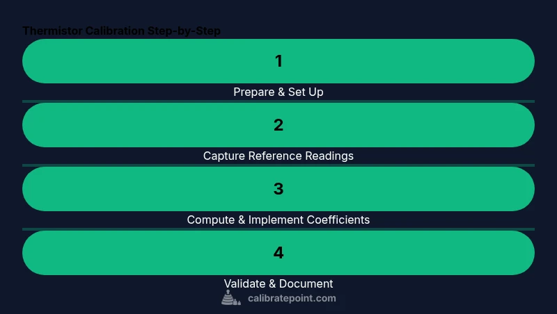
Steps
Estimated time: 40-60 minutes
- 1
Prepare reference temperatures
Set up at least three stable reference temperatures across the sensor’s operating range. Confirm bath temperature stability with your calibrated thermometer and allow the bath to reach steady state before measurements.
Tip: Document the exact reference temperatures and stabilization times for each point. - 2
Connect the thermistor to the measurement circuit
Mount the thermistor in a way that minimizes thermal lag and ensures good electrical contact. Use four-wire leads if available to eliminate lead resistance from measurements.
Tip: Keep wiring short and well shielded to reduce noise. - 3
Stabilize at first reference temperature
Immerse the sensor and verify temperature stability within a tight tolerance. Wait for the sensor to settle before recording.
Tip: Record multiple readings and discard the first stabilization value. - 4
Record resistance at reference temperature
Measure and log the sensor’s resistance with the corresponding reference temperature. Repeat measurements to compute an average.
Tip: Use a consistent measurement interval and document ambient conditions. - 5
Repeat for additional reference temperatures
Proceed to the second and third reference temperatures, repeating stabilization and measurement steps. Maintain identical setup to ensure comparability.
Tip: Aim for evenly spaced temperatures to improve fit quality. - 6
Compute calibration coefficients
Using your collected (R, T) data, perform a nonlinear regression to fit Steinhart-Hart coefficients (A, B, C) or fit the Beta model parameters (R0, B, T0).
Tip: Keep a copy of raw data and the fitting results for auditability. - 7
Update software with calibration data
Embed the chosen model and its coefficients into your device’s firmware or software. Include a version tag and a validation routine.
Tip: Test the updated conversion against the original reference temps before full deployment. - 8
Validate and document
Re-measure at all reference temperatures to confirm fit accuracy. Document results, acceptance criteria, and any drift or anomalies observed during calibration.
Tip: Create a calibration log so future maintenance is straightforward.
Questions & Answers
What is thermistor calibration and why is it needed?
Thermistor calibration aligns the sensor’s resistance-to-temperature curve with known reference points, reducing error due to manufacturing tolerances and aging. It improves accuracy across the sensor’s operating range and supports reliable data for control or diagnostics.
Thermistor calibration makes resistance readings match true temperatures across the range, improving accuracy for control and diagnostics.
Which reference temperatures should I use for calibration?
Select at least three temperatures that span the sensor’s operating range. Use stable, well-defined points and repeat measurements to ensure repeatability. Avoid relying on a single temperature point for calibration.
Use multiple stable temperatures across the range and repeat measurements for reliability.
Can I calibrate an in-field thermistor without a climate chamber?
Yes, with simple reference baths or calibrated temperature sources. The key is stable, known temperatures and low measurement noise. In-field methods may be less precise than a lab environment, but they can still yield meaningful improvements.
Field calibration with stable temperature references can still improve accuracy, though not as precisely as a lab setup.
What are common errors that invalidate calibration?
Inconsistent measurement methods, unstable reference temperatures, insufficient stabilization time, and neglecting thermal contact can all introduce bias. Always log conditions and validate with multiple points.
Inconsistent method, temp instability, or poor thermal contact can ruin calibration.
How often should thermistor calibration be performed?
Calibration frequency depends on usage and environment. In critical systems, re-calibrate after significant temperature cycling, physical relocation, or sensor aging. Maintain a calibration log for traceability.
Recalibrate after major changes or sensor aging; keep a log.
Watch Video
Key Takeaways
- Perform multi-point calibration across the operating range.
- Use stable reference temperatures and precise resistance measurements.
- Choose a model (Steinhart-Hart or Beta) that fits your range and compute coefficients carefully.
- Validate results with independent checks and maintain calibration records.