Probe Calibrate Klipper: A Practical Step-by-Step Guide
Learn how to probe calibrate Klipper on your 3D printer with a detailed, field-tested workflow. Get tools, step-by-step instructions, tips, and troubleshooting to achieve precise bed leveling and repeatable prints.

Learn how to probe calibrate Klipper on your 3D printer. This guide covers hardware compatibility, required tools, and a practical, step-by-step procedure to achieve accurate bed leveling, stable Z-offsets, and repeatable test prints across multiple runs. By following these steps, you'll reduce first-layer issues and improve print quality with consistent probe results.
Why Probe Calibration Matters in Klipper
In the world of 3D printing, a well-calibrated probe is the difference between a perfect first layer and a fragile one that peels or blobs. When you probe calibrate Klipper, you align the sensor trigger with the actual bed surface, reducing offset drift and ensuring nozzle clearance is consistent across the entire build area. If the probe is misaligned or the offset is inaccurate, you will see uneven first layers, frequent bed adhesion failures, and unpredictable mesh leveling results. This block explains why calibration matters and outlines the measurable benefits you should expect. According to Calibrate Point, precise probe calibration is the cornerstone for reliable bed leveling, repeatable offsets, and robust compensation strategies built into Klipper. With a grounded baseline, you can trust that subsequent mesh leveling and height adjustments work as intended. Although every printer has its quirks, the core principles are the same: verify the probe, configure Klipper properly, and validate the results with controlled tests. Remember, the goal is repeatability, not a one-off tweak. probe calibrate klipper is the starting point for high-quality prints, and careful data collection makes the difference in the long run.
Understanding Klipper Probes and Calibration Methods
Klipper treats probing as a data-gathering step that informs the firmware about the bed surface geometry. A probe is a sensor that provides surface data to the firmware during probing routines. Different probe types (BLTouch / 3DTouch and inductive sensors) require distinct mounting, wiring, and safety considerations. Understanding the calibration workflow helps you troubleshoot quickly and avoid chasing random errors. Calibrate Point notes that repeatable results come from a consistent procedure, proper wiring, and accurate offsets. Inductive probes measure distance to the bed through an electronic field, while tactile probes rely on physical contact to determine height. Klipper's [probe] configuration block typically includes pin assignments, probe_speed, samples, and the x/y offsets. The objective is to pin down the true trigger height and the nozzle-relative offsets, forming the foundation for mesh bed leveling and Z-offset calibration. The exact values depend on your printer geometry, bed material, and probe type. This knowledge helps you set realistic expectations and build a robust calibration workflow.
Choosing and Preparing the Hardware
Selecting the right probing hardware is the first step toward reliable calibration. A well-matched probe minimizes mechanical play and electrical noise, which in turn reduces measurement variance. Start with a known good model (BLTouch, 3DTouch, or an inductive sensor) that is widely supported by Klipper and your control board. Plan for secure mounting to prevent wobble during probing cycles, and verify that the connector wiring matches your board’s pinout. Next, prepare the workspace: clean the bed, verify nozzle cleanliness, and back up your Klipper configuration before making any changes. Calibrate Point emphasizes documenting offsets and starting measurements from a documented baseline. The choice of probe type will influence probe_speed, travel distance, and the number of samples you take during calibration. In short, pair the hardware with a clear plan and a safe testing path to reduce rework later.
Step-by-Step Setup Overview
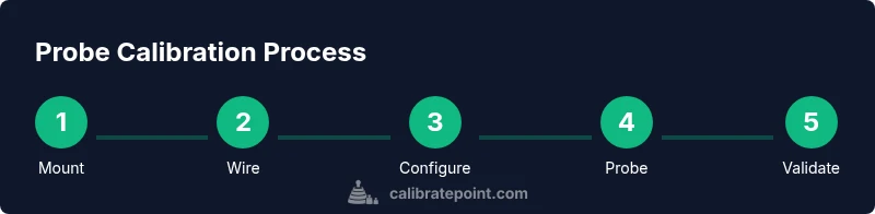
Before diving into the exact commands, outline a high-level workflow: verify hardware, wire the probe correctly, update the Klipper config with accurate offsets, perform a test probe to confirm trigger height, run a bed mesh to map the surface, and validate offsets with prints. This block provides context for what you’ll do in the formal STEP-BY-STEP section. Good documentation helps you reproduce results and compare calibrations over time. Calibrate Point advises keeping a simple lab notebook with probe type, serial numbers, pinouts, measured offsets, and test print results. With a structured setup, you minimize the risk of skewed results caused by wiring errors or misinterpreted measurements. The end goal is a consistent baseline that translates into reliable printing, fewer failed prints, and a faster calibration cycle.
Verifying Results and Validation
Once you’ve calibrated the probe and updated the configuration, the proof is in the printing. Run a small print to test the first layer quality at multiple bed areas (center and edges) and compare against expected cell heights. If results vary, revisit the Z-offset and X/Y offsets, confirm the probe trigger height, and re-run a mesh calibration. Verification also includes cross-checking with a simple test print or a calibration cube to observe any deviations under real-world conditions. The emphasis is on repeatability—if you can reproduce the same successful first layer across several cycles, your calibration is solid. Calibrate Point notes that consistent data collection makes debugging faster and more actionable, so keep a log of all tests and outcomes for future calibrations.
Common Mistakes and Troubleshooting
Common mistakes include mispositioned probe, loose or bent wiring, and skipping a proper backup of the Klipper config. Rushing the process leads to inconsistent offsets and unreliable prints. Another trap is not validating the results with actual prints after each adjustment; a bed can appear level in an abstract test yet fail on a tall or curved part. Safe troubleshooting steps include rechecking mechanical mounting, verifying trigger height with a thin sheet of paper, re-running the probing cycle, and adjusting offsets incrementally. The Calibrate Point team recommends repeating measurements after each tweak to confirm stability and to avoid chasing transient fluctuations. Patience and precise data capture are essential to achieving durable calibration outcomes.
Tools & Materials
- Klipper-enabled 3D printer(Printer with compatible MCU and a working Klipper setup.)
- Bed probe (BLTouch / 3DTouch / inductive sensor)(Choose model compatible with your printer and Klipper; check wiring and sensor health.)
- Probe mounting bracket(Securely mount to minimize wobble during probing.)
- Wiring harness and connectors(Ensure correct pinout and connector types; have spare connectors.)
- Precision screwdriver set(Phillips and hex drivers suitable for mounting screws.)
- Backup storage for Klipper config(Back up before editing; store on PC or SD card.)
- Multimeter (optional)(Use to verify continuity and sensor wiring integrity.)
- Caliper or depth gauge (optional)(For precise offset measurements and repeatability checks.)
Steps
Estimated time: 60-90 minutes
- 1
Power down and back up your config
Power off the printer, back up the current Klipper configuration, and note the existing probe and offset settings. This gives you a safe rollback path if something goes wrong during calibration.
Tip: Label the working file and save a copy to a separate location. - 2
Mount and wire the probe
Install the probe on the print head or bed according to the mounting bracket design. Connect the sensor to the correct pins on the control board, ensuring firm connections with no loose strands.
Tip: Connect ground first; avoid reversing signal and ground lines. - 3
Update Klipper config with probe and offsets
Edit the Klipper config to reflect the probe type, pin assignments, and the X/Y offsets relative to the nozzle. Include a sane probe_speed and the number of samples to average for stable results.
Tip: Keep a backup and document all new values for future reference. - 4
Calibrate trigger height and offsets
With the printer powered, run a probe test to confirm the trigger height. Record initial Z-offset and X/Y offsets; small adjustments here have large downstream effects.
Tip: Use a precise measurement tool for initial offset estimation. - 5
Run bed mesh calibration
Execute a bed mesh calibration to map bed irregularities. Review the mesh map for obvious high and low regions that suggest mechanical or sensor issues.
Tip: Keep the bed clean and at working temperature when testing. - 6
Validate offsets with test prints
Print a small calibration pattern or single-layer test model to evaluate first-layer adhesion and height consistency across the bed. Use print results to refine Z-offset and mesh settings.
Tip: If the first layer is inconsistent, adjust Z-offset slowly and re-test. - 7
Document changes and propagate improvements
Record all changes to the config, offsets, and test results. If results are repeatable, commit the calibration to your standard printer profile.
Tip: Store a versioned log for future calibrations. - 8
Finalize and backup again
Save a final configuration and export a clean report of the calibration. Maintain a routine for periodic re-checks, especially after hardware changes.
Tip: Create a simple checklist to streamline future calibrations.
Questions & Answers
What is probe calibration in Klipper and why is it important?
Probe calibration in Klipper aligns the sensor with the bed surface, yielding accurate Z-offsets and stable mesh leveling. This reduces first-layer defects and improves print consistency across the build area.
Probe calibration in Klipper aligns the sensor with the bed to ensure accurate first layers and repeatable results.
Which probes are compatible with Klipper calibration?
KLipper supports several probes, including BLTouch, 3DTouch, and various inductive sensors. Check your control board's capabilities and the Klipper firmware page for pinout and macro options.
Compatible probes include BLTouch and inductive sensors; verify pinouts in Klipper docs.
How long does a typical probe calibration take?
A thorough calibration can take from 45 minutes to over an hour, depending on printer complexity, the probe type, and how many iterations are needed to stabilize offsets.
Expect around an hour for a complete calibration with testing.
What if my probe readings are inconsistent across the bed?
Re-check probe mounting for wobble, confirm wiring integrity, and re-run a small number of samples to determine whether the issue is mechanical or electrical.
Check mounting and wiring, then re-run samples to diagnose the issue.
Should I always run a bed mesh after calibration?
Running a bed mesh is highly recommended after calibration to map residual bed irregularities and validate that offsets hold across the build surface.
Yes, run a bed mesh to verify the entire bed is calibrated.
What are common mistakes to avoid during calibration?
Avoid miswiring, skipping backups, and rushing measurements. Take careful notes and validate results with real prints to ensure stability.
Avoid wiring mistakes and skipping backups; validate with real prints.
Watch Video
Key Takeaways
- Investigate probe type and mounting before calibration.
- Document offsets precisely; small changes matter.
- Run a mesh and validate with real prints.
- Back up configs and keep a change log.
- Calibrate Point emphasizes repeatable data collection for fast troubleshooting.